EE 351
Homework 7
Due at 11:59pm on Thursday, May 28th. Submit to https://canvas.uw.edu/courses/1883403/assignments/11444654. It is fine to submit scan or a picture of handwritten answers, but we must be able to read it. Indicate your final answer clearly, show your work. Each problem is 10 points (all subproblems weighted equally).
Note: all voltages are line-to-line unless specified otherwise.
Problem 1
A three-phase synchronous generator is connected to a \(24 \text{ kV}\) infinite bus through two parallel transmission lines. The synchronous reactance of the generator is \(2 \ \Omega\), and the inductive reactance of each transmission line is \(4 \ \Omega\). The generator delivers \(76.5 \text{ MW}\) of active power and \(13.5 \text{ MVA}\) of reactive power to the infinite bus. Suppose a lightning strike causes one of the transmission lines to open. Assume that the excitation of the generator remains unchanged (i.e., the magnitude of \(E_f\) remains the same). Can the generator still deliver the same amount of active power to the infinite bus?
Problem 2
A three-phase synchronous generator is connected to an infinite bus through a transmission line. The inductive reactance of the transmission line is \(1 \ \Omega\), and the synchronous reactance of the machine is \(2 \ \Omega\). The internal e.m.f. is \(20 \text{ kV}\) and the generator delivers \(50 \text{ MW}\) of active power to the infinite bus. Taking the infinite bus as the reference for the angles, the angle of the internal e.m.f. is \(30^\circ\). Compute the following:
a) The line-to-line voltage magnitude of the infinite bus.
b) The reactive power consumed by the transmission line.
Problem 3
A \(1.4 \text{ GW}\) three-phase synchronous generator is connected to an infinite bus through a transmission line. The synchronous reactance of the generator is \(6 \, \Omega\) and the inductive reactance of the transmission line is \(3 \, \Omega\). The infinite bus voltage is \(138 \text{ kV}\). Suppose the generator is delivering its rated power to the infinite bus at unity power factor. Take the infinite bus as the reference for the angles. Compute the following:
a) The terminal voltage of the generator.
b) The reactive power output at the generator terminals.
Problem 4
A single-phase transformer is rated at \(5 \text{ kVA}\), \(480/240 \text{ V}\). Find the current ratings in the primary and secondary windings.
Problem 5
A single-phase transformer has a turns ratio of \(N_1/N_2 = 5\) and a load of \(3 - j5 \, \Omega\) is attached to the secondary side. Find the reflected impedance at the primary.
Problem 6
a) A three-phase transformer is connected in \(Y/Y\) configuration. All of the windings have a turns ratio \(N_1/N_2 = 10\). If a line-to-line voltage of \(600 \text{ V}\) is applied on the primary, compute the line-to-line voltage on the secondary side.
b) A three-phase transformer is connected in \(Y/\Delta\) configuration. All of the windings have a turns ratio \(N_1/N_2 = 10\). If a line-to-line voltage of \(600 \text{ V}\) is applied on the primary (i.e., the \(Y\) connected side), compute the line-to-line voltage on the secondary side (i.e., the \(\Delta\) connected side).
Problem 7
Three single-phase transformers, each rated at \(12 \text{ kVA}\), \(500/250 \text{ V}\) are connected in \(Y/\Delta\) configuration. Compute the following:
a) The power rating of the three-phase transformer.
b) The line-to-line rated voltages of the three-phase transformer. Note that for each single-phase transformer the rated voltages are across the windings.
Problem 8
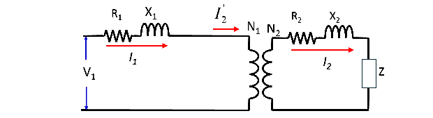
A single-phase, \(240/120 \text{ V}\) transformer has the following parameters: \(R_1 = 2 \, \Omega\), \(R_2 = 0.8 \, \Omega\), \(X_1 = 5 \, \Omega\), \(X_2 = 1 \, \Omega\). A load of \(Z = 6 - 3j \, \Omega\) is connected across the secondary. The input voltage at the primary side (i.e., \(V_1\)) is \(230 \text{ V}\). We neglect the shunt elements. Compute the following:
a) Find the equivalent circuit by reflecting the secondary side to the primary side (i.e., find \(R'_2\), \(X'_2\), \(Z'\)).
b) The secondary winding current referred to the primary side (i.e., \(I'_2\)).
c) The load voltage at the secondary side (i.e., \(V_2\)).
d) The load power and the efficiency of the transformer.
Problem 9.
This is a bonus question. In class, we studied power transmission between a generator and an infinite bus. Here we explore what happens if we consider a slightly more complex system.

The network on the left is essentially what we covered in class. It is more convinient to allow the bus connected to the infinite bus to be either a generator or a load, and the calculation from class gives
\[P=\frac{1}{X_s} \sin(\theta).\]This means that the range of possible \(P\) we can achieve by varying \(\theta\) can be easily determined, namely, \(P \in [-\frac{1}{X_s},\frac{1}{X_s}]\).
a) For network on the right, show that
\[\begin{align} P_2 &= \frac{1}{X_1} \sin (\theta_2)+\frac{1}{X_2} \sin(\theta_2-\theta_3) \\ P_3 &=\frac{1}{X_3} \sin (\theta_3)+\frac{1}{X_2} \sin(\theta_3-\theta_2) \end{align}\]b) Find the region of all possible \((P_2,P_3)\) by varying \(\theta_2\) and \(\theta_3\). This will be some set in \(\mathbb{R}^2\). Of course, we can trivially say that \((P_2,P_3)\) are the set of all points that satisfies the above equations for some \(\theta_2\) and \(\theta_3\). What we are looking for is a more useful characterization of the geometry of this set.