EE 351
Homework 3
Due at 11:59pm on Thursday,. Submit to https://canvas.uw.edu/courses/1883403/assignments/11390357 . It is fine to submit scanned or a picture of handwritten answers, but we must be able to read it. Indicate your final answer clearly, show your work. Each problem is 10 points (all subproblems weighted equally).
Problem 1
A full-wave AC/DC SCR converter circuit is used to power a resistive load of \(12 \Omega\). The AC voltage is 120 V (rms), and the triggering angle of the SCR is adjusted to \(60^\circ\). Compute the following:
a) The average voltage across the load.
b) The load power.
Solutions.
a) For a full-wave controlled rectifier with a resistive load:
\[V_{dc} = \frac{V_m}{\pi}\left(1 + \cos\alpha\right)\] \[V_{dc} = \frac{169.71 \times 1.5}{\pi} = 81.03 \; \text{V}\]b) The RMS output voltage of a full-wave SCR converter is:
\[V_{rms} = \frac{V_m}{\sqrt{2}}\sqrt{\frac{1}{\pi}\left[\pi - \alpha + \frac{\sin 2\alpha}{2}\right]}\]With \(\alpha = \pi/3\) and \(\sin(2\alpha) = \sin(120^\circ) = \frac{\sqrt{3}}{2}\):
\[V_{rms} = \frac{169.71}{\sqrt{2}}\sqrt{\frac{2.5274}{\pi}} = 107.64 \; \text{V}\] \[P = \frac{V_{rms}^2}{R} = \frac{(107.64)^2}{12} = 965.5 \; \text{W}\]Problem 2
A half-wave AC/DC SCR converter circuit is used to power a resistive load of \(12 \Omega\). The AC voltage is 120 V (rms), and the triggering angle of the SCR is adjusted to \(60^\circ\). Compute the following:
a) The load power.
b) The triggering angle (if one exists) where the load power delivered using this half-wave circuit is equal ot the full wave circuit in problem 1.
Solution.
a) \(V_{rms} = \frac{V_m}{2}\sqrt{\frac{1}{\pi}\left[\pi - \alpha + \frac{\sin 2\alpha}{2}\right]}\)
With \(\alpha = \pi/3\) and \(\sin(120^\circ) = \frac{\sqrt{3}}{2}\):
\[V_{rms} = \frac{169.71}{2}\sqrt{\frac{2.5274}{\pi}} = 76.11 \; \text{V}\] \[P = \frac{V_{rms}^2}{R} = \frac{(76.11)^2}{12} = 482.7 \; \text{W}\]b) We want to find \(\alpha\) such that:
\[P_{half}(\alpha) = P_{full}(60^\circ) \approx 965.5 \; \text{W}\]The largest half-wave RMS voltage occurs at \(\alpha = 0^\circ\):
\[V_{rms,\max} = \frac{V_m}{2} = \frac{169.71}{2} = 84.85 \; \text{V}\] \[P_{\max} = \frac{(84.85)^2}{12} = 600 \; \text{W}\]Since the maximum deliverable half-wave power is only 600 W, while the full-wave circuit at \(\alpha = 60^\circ\) delivers about \(965.5 \; \text{W}\), no triggering angle exists.
Problem 3
An AC/AC converter consists of two SCRs connected in parallel in the back-to-back configuration. The AC source has a voltage of \(120 \text{ V (rms)}\), and the load is a \(10 \Omega\) resistance. The triggering angle for one of the SCRs is \(15^\circ\) and the other SCR is \(30^\circ\). Find the power delivered to the load.
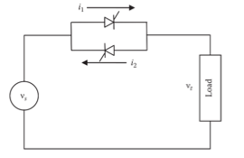
Solutions.
Because the two SCRs fire at different angles, each half-cycle contributes a different amount of power. We can compute the power delivered by each half-wave rectifier, and then add them.
In the forward cycle,
\[V_{rms}^2 = \frac{V_m^2}{4\pi}\left(\pi - \alpha_1 + \frac{\sin 2\alpha_1}{2}\right)=\frac{V_m^2}{4\pi} \cdot 3.1298\]and in the reverse cycle,
\[V_{rms}^2=\frac{V_m^2}{4\pi} \left(\pi - \alpha_2 + \frac{\sin 2\alpha_2}{2}\right)=\frac{V_m^2}{4\pi} \cdot 3.051.\]Power delivered is
\[\frac{V_{rms,formward}^2}{R}+\frac{V_{rms,reverse}^2}{R}=1.42 \ \text{kW}.\]Problem 4
A buck–boost converter with an input voltage of \(60 \; V\) is used to regulate the load voltage from \(5\) to \(130 \; V\). The on-time of the transistor is always fixed at \(0.4 \; ms\) and the switching frequency is adjusted to regulate the load voltage. Compute the minimum and maximum switching frequency.
Solutions.
\[\vert V_t \vert = \frac{k}{1 - k}V_s\]Solving for the duty cycle \(k\):
\[k = \frac{\vert V_t \vert}{V_s + \vert V_t \vert}\]and we have
\[f = \frac{k}{t_{on}}\]Minimum Frequency (corresponds to \(V_t = 5 \; \text{V}\))
\[k_{\min} = \frac{5}{60 + 5} = 0.0769\] \[f_{\min} = 192.3 \; \text{Hz}\]Maximum Frequency (corresponds to \(V_t = 130 \; \text{V}\))
\[k_{\max} = \frac{130}{60 + 130} = 0.6842\] \[f_{\max} = 1710.5 \; \text{Hz}\]Problem 5
A buck–boost converter has an input voltage of \(10 \; V\). The switching frequency of its transistor is \(6.5 \; kHz\), and its duty ratio is \(45\%\). Compute the following:
a) The transistor on time
b) The average voltage across the load
Solutions.
a)
\[t_{on} = k \cdot T = \frac{k}{f} = 0.45 \times \frac{1}{6500}= 69.23 \; \mu\text{s}\]b) We have
\[V_t = -\frac{k}{1 - k}\,V_s= -\frac{0.45}{1 - 0.45}\,(10) = -8.18 \; \text{V}\]Problem 6
A boost converter consists of a \(65 \; V\) source powering a \(12 \; \Omega\) load resistance. For the switch in the circuit, it is closed for \(50 \; \mu s\) and opened for \(250 \; \mu s\) in each cycle. Compute the following:
a) The switching frequency of the converter
b) The average voltage across the load
c) The average load current
d) The power generated by the source.
Solutions.
a)
\[f = \frac{1}{T} = \frac{1}{300 \times 10^{-6}}=3.33 \; \text{kHz}\]b) Duty ratio:
\[k = \frac{t_{on}}{T} = \frac{50}{300} = 0.1667\]For an ideal boost converter (CCM):
\[V_t = \frac{V_s}{1 - k}= \frac{65}{1 - 0.1667} = 78 \; \text{V}\]c)
\[I_t = \frac{V_t}{R} = 6.5 \; \text{A}\]d) Power Generated by the Source
For an ideal lossless converter, source power equals load power:
\[P_s = P_t = V_t I_t = 507 \; \text{W}\]Problem 7
A source is connected to a load via three identical cables in parallel. The impedance of each cable is \(𝑍 = 0.12 + 𝑗 0.12 \; \Omega\). The voltage drop across the cables is \(10 \angle 0 \; V\). Suppose the load impedance is \(𝑍_L = 1 − 𝑗0.10 \; \Omega\). Compute the following:
a) The load current
b) The complex power consumed by the load
c) The load power factor
d) The rms source voltage (magnitude and angle)
Solutions.
a) First note that for three parallel cables, the equivalent impedance is
\[Z_{cable} = \frac{0.12 + j0.12}{3} = 0.04 + j0.04 =0.0566 \angle 45^\circ \ \Omega\]The same current flows through cables and load (they are in series):
\[I = \frac{V_{cable}}{Z_{cable}} = \frac{10\angle 0^\circ}{0.0566\angle 45^\circ}= 176.78\angle -45^\circ \; \text{A}\]b) Using \(S_L = \vert I \vert ^2 \, Z_L\):
\[P_L = \vert I \vert^2 R_L = (176.78)^2 (1) =31.25 \; \text{kW}\] \[Q_L = \vert I \vert^2 X_L = (176.78)^2 (-0.10) =-3.125 \; \text{kVAR}\] \[S_L = 31.250 - j3.125 \; \text{kVA}\]c) \(\text{pf} = \cos\theta_L = \frac{P_L}{\vert S_L \vert} = 0.995 \; \text{(leading)}\)
The load is slightly capacitive (\(X_L < 0\)), so the current leads the voltage.
d) RMS Source Voltage
First, compute the voltage across the load:
\[V_L = I \cdot Z_L = (125 - j125)(1 - j0.10)= 112.5 - j137.5 \; \text{V}\] \[V_s = V_{cable} + V_L = (10 + j0) + (112.5 - j137.5)\] \[V_s = 122.5 - j137.5 \; \text{V}= 184.16 \angle -48.31^\circ \; \text{V (rms)}\]Problem 8
Continuing with problem 7. Suppose two of the cables between the source and load are disconnected, i.e., become an open circuit. The source voltage is unchanged in both magnitude and angle. Find the complex power supplied by the source.
Solutions.
With only 1 cable in service: \(Z_{cable} = 0.12 + j0.12 \; \Omega\). We are given that the source voltage is unchanged: \(V_s = 184.16 \angle -48.31^\circ \; \text{V} = 122.5 - j137.5 \; \text{V}\) and the load impedance is unchanged: \(Z_L = 1 - j0.10 \; \Omega\).
The total impedance is
\[Z_{tot} = Z_{cable} + Z_L = 1.12 + j0.02 \; \Omega\]The current is
\[I_s = \frac{V_s}{Z_{tot}} = = 164.40 \angle -49.33^\circ \; \text{A} = 107.15 - j124.68 \; \text{A}\]Using \(S_s = \vert I_s \vert^2 \, Z_{tot} = 30.27 + j0.54 \; \text{kVA}\)